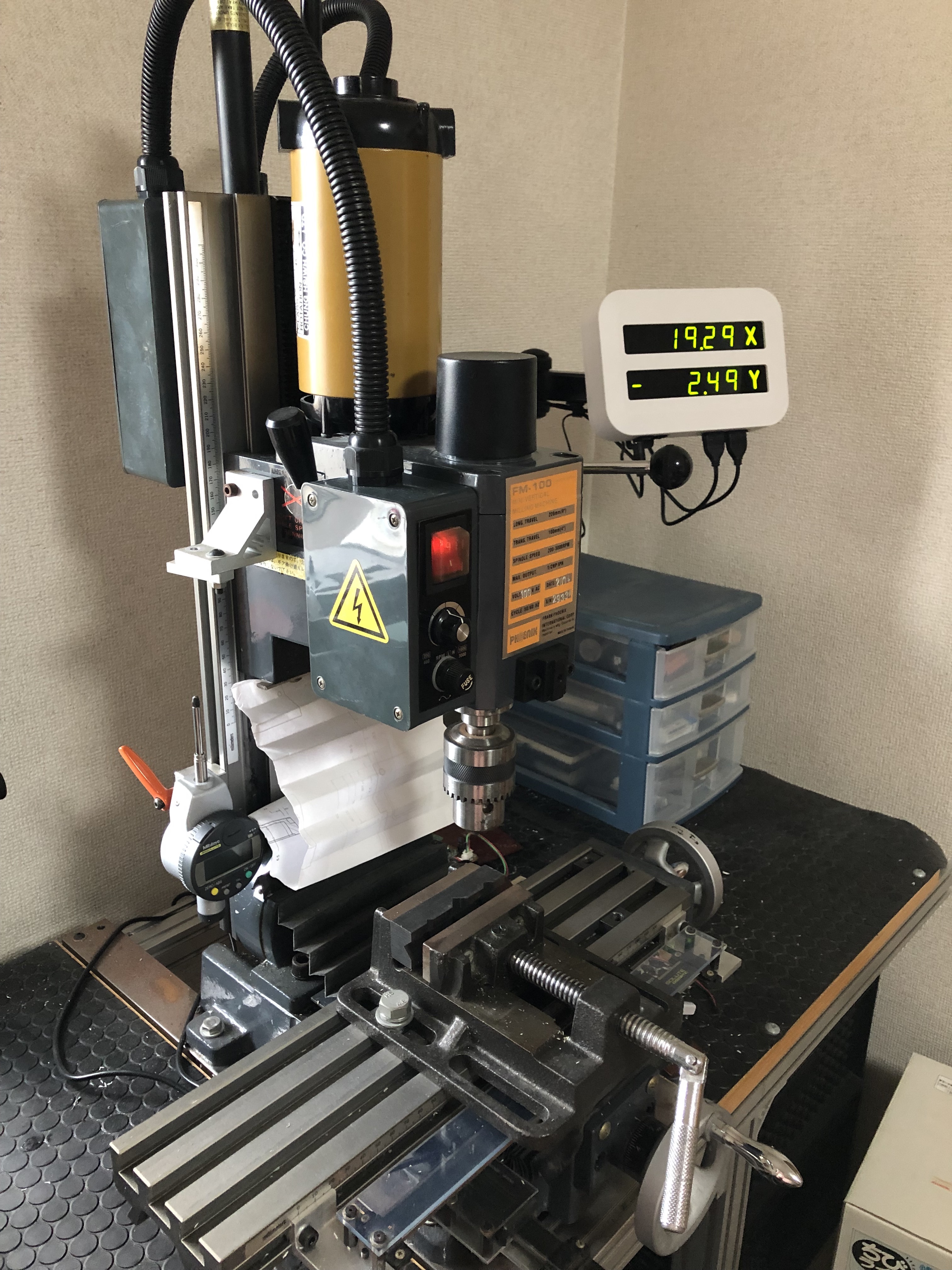
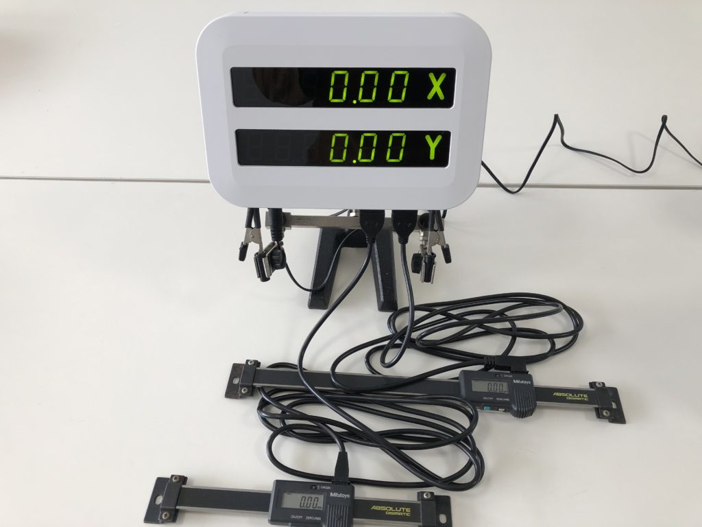
(Originally published September 7, 2018) Some of my projects involve mechanical parts which I make myself using a benchtop milling machine. I’ve attached digital scales on the mill’s X and Y axes to help me mill the parts accurately and efficiently, but the readouts on the scales are small and hard to read. The maker of the scales sells display units, but they are rather expensive, bulky and have a lot of functions I don’t need. So I decided to make my own display.
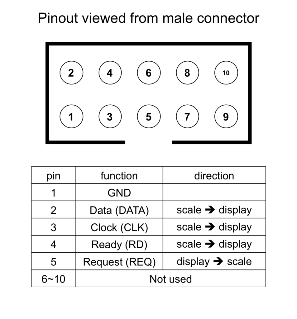
The digital scales are from the Mitutoyo’s Digimatic series, which have an interface port that allows connection to a digital display. Many examples of do-it-yourself Digimatic interfaces can be found online, though caution is needed as I’ve found that at least one source provides some incorrect information. Mitutoyo’s own document describing the interface protocol in detail can also be found. The interface cable has a proprietary plug on the scale end, and a standard 10-pin shrouded header plug on the other. The pinout is below.
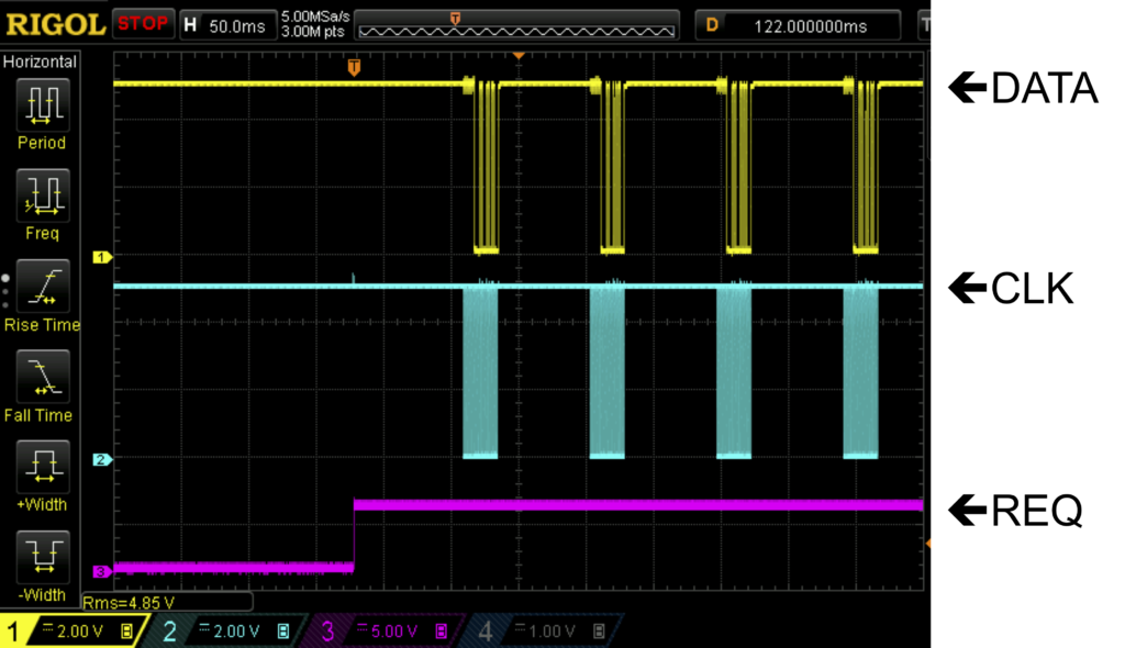
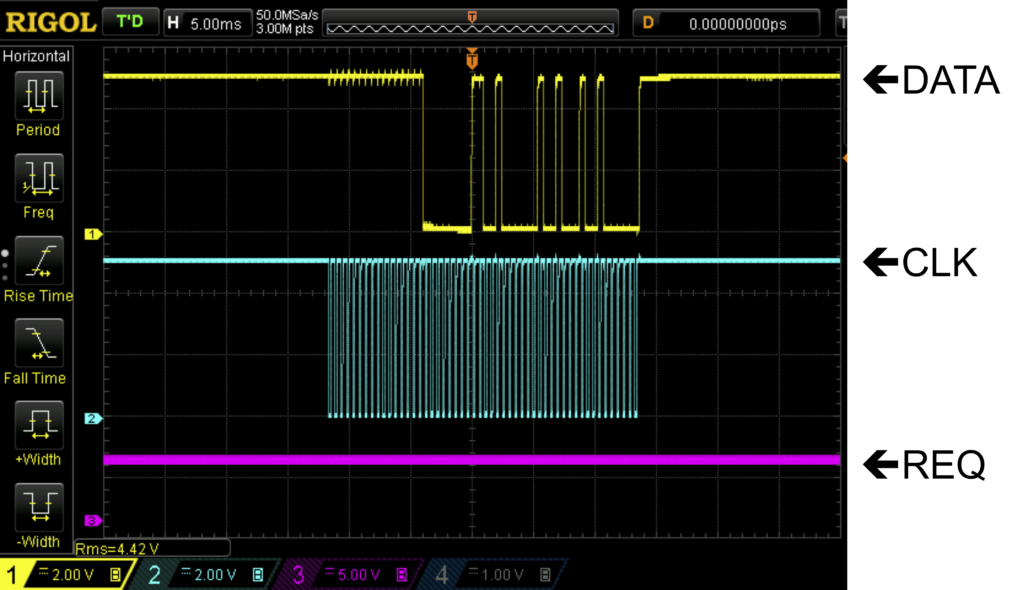
According to the Mitutoyo Digimatic spec, the scale outputs a low “ready” signal on the RD pin a few times each second, but I didn’t observe this on the oscilloscope; the RD pin was always high. I did observe that the scale outputs data when the REQ pin is pulled low (REQ in below waveforms is signal to base of NPN transistor that pulls REQ low), and outputs data continuously as long as the REQ pin is held low. The timing diagrams can be found in the Digimatic spec, but I show actual waveform measurements of the REQ, CLK, and DATA lines below. The data is 52 bits grouped into 13 4-bit bytes. Six bytes are the position digits in BCD format. One byte is for sign (0000 for positive, 0001 for negative), and another for the decimal position in BCD format. The remaining bits are for device ID, units, etc. For this application, units and decimal position (mm and 3 respectively) are fixed so unneeded. I’m concerned only with the position digits and sign.
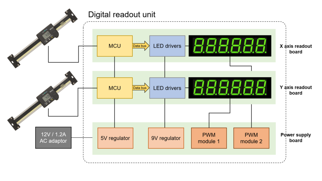
To read and process the data, the scale is interfaced to a PIC18F2550 microcontroller. The readout circuit diagram is shown below. The CLK is input to the MCU INT1, and the DATA to an input pin. An output pin is used to pull the REQ line low when the MCU is ready to get data from the scale.
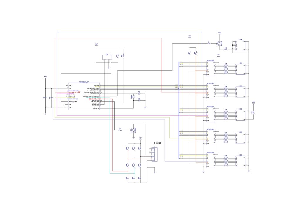
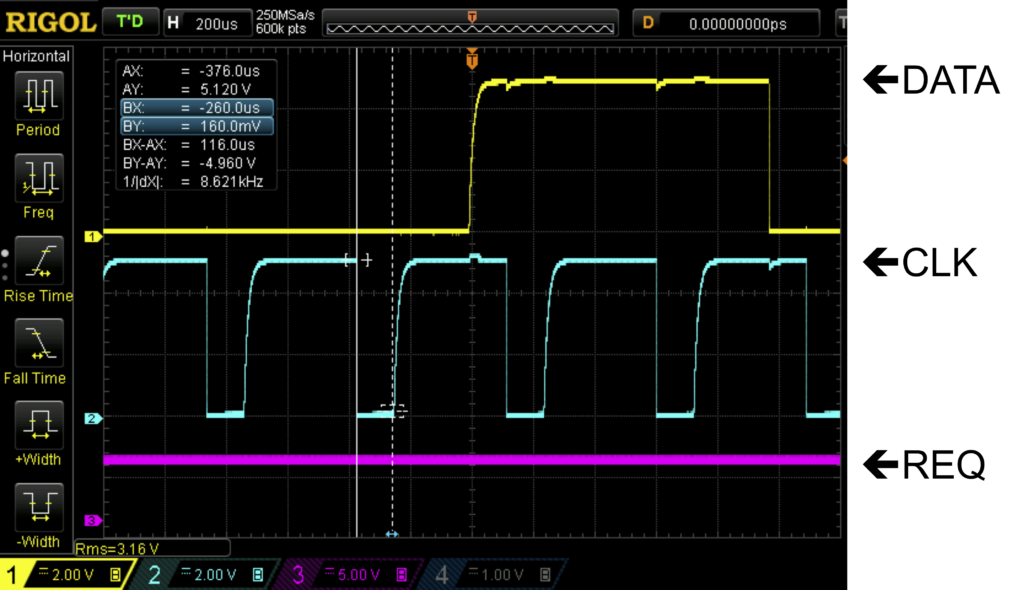
Data is valid on CLK high, so INT1 interrupts on the rising edge, and the data on the input pin is read and stored in a 52-element array. When 52 bits have been read, the MCU processes the array – extracting the BCD digits and outputting them to RA0~RA3, which together function as a 4-bit parallel port. RA0~RA3 are interfaced via bus to five TC4511 7 segment LED latch/decoder/driver ICs, each of which drives a 7 segment LED. The sixth 7 segment LED is “-” sign only and therefore controlled from the MCU directly. Since all five TC4511s share the data bus, the LE pin on these ICs is pulled low one at a time to indicate which of them should read the data on the bus.
I’ve observed the MCU become out-of-sync with the scale’s clock and data so that the 52 bits are read across two data packets – yielding garbage data, so I employed the MCU’s TIMER0 to time out the clock input at one millisecond and trigger a high-then-low pulse on the REQ line to reset the data stream if the data count is below 52.
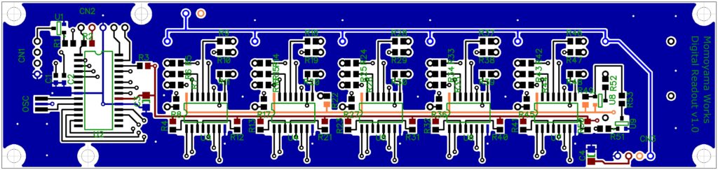
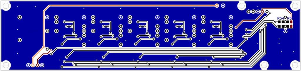
PCB design pics
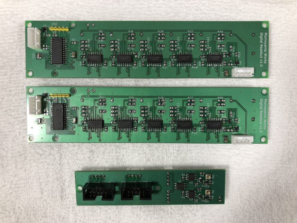
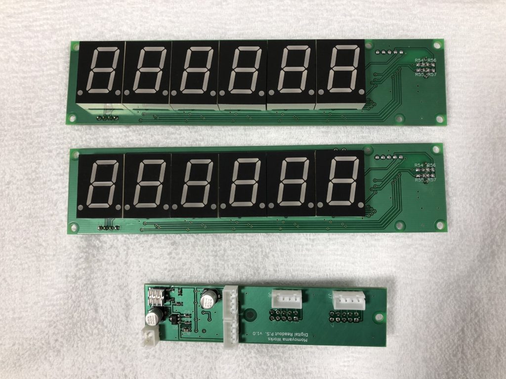
Finished readout